Voltage drop across inductor calculator
Ie V R is in phase with I. However if a low frequency is present part of the voltage across the capacitor will drop.

Capacitors In Series And Series Capacitor Circuits
The voltmeter is connected in parallel with the circuit in order to measure the subsequent voltage drop across the resistor.

. V L didt. V T V 1. By using Kirchoffs voltage law total voltage drop is the sum of the voltage drop across each inductor.
Remember the voltage dropped across an inductor is a reaction against the change in current through it. An inductor typically consists of an insulated wire wound into a coil. This allows the buck regulator controller chip to know the amperage of the circuit - without being inside the circuit.
However it should be noted that the fundamental 5060Hz voltage drop across the Line reactor will be a small valueThe reason for this is that drives are inherently high displacement power factor devices Fundamental. In a single erratic change in the input voltage V. In case of resistor both voltage and current are in same phase.
This tells us. The efficiency of the regulator can be restricted to 3V or 5V which means these regulators are applicable with fewer Vin Vout differentials. This voltage depends upon the inductance value.
When the current flowing through the coil changes the time-varying magnetic field induces an electromotive force emf in the. Analogue voltmeters mainly consist of a deflecting needle and a curved graduated scale on the display unit. If we were to plot the current and voltage for this very simple circuit it would look something like this.
A voltmeter is used for measuring the terminal voltage whereas a potentiometer is used for measuring the EMF. So draw the voltage phasor V R along same axis or direction as that of current phasor. What is Practical Ideal Voltage Source.
The output voltage V_out is thus almost identical to the input voltage V_in. As a result the output voltage drops parallel to the resistor with a time delay. The voltage drop across an inductor can be calculated using.
Using the two previous equations δ is. The voltage across the resistor has the exact same phase angle as the current through it telling us that E and I are in phase for the resistor only. The load current I o is equal to the average diode current I DAs can be seen on figure 4 the diode current is equal to the inductor current during the off.
Pure inductive circuit waveforms. A voltage source having some internal resistance is called a practical voltage source. In this case the current flowing through each inductor is the same while the voltage across each inductor is different.
For example when the input of the voltage regulator is 5V generates output like 3V then the voltage drop among the two terminals is 2V. The supply voltage of the practical voltage source decreases with an increase in the current. A voltmeter is used to display the potential difference existing between two points of an electrical network.
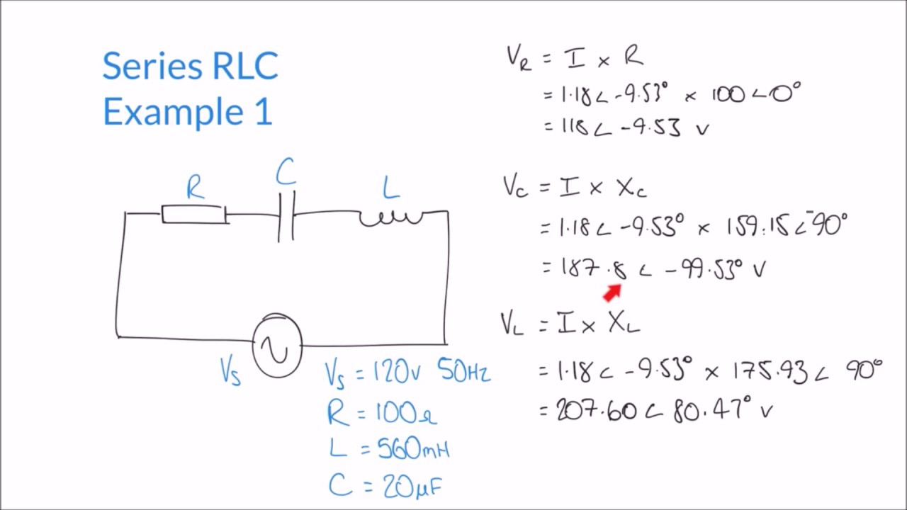
The flow of current through the series circuit is I VR according to Ohms Law. Due to this resistance there is a voltage drop. The voltage across the inductor has a phase angle of 52984 while the current through the inductor has a phase angle of -37016 a difference of exactly 90 between the two.
The voltage drop of this IC is similar to a resistor voltage drop. While EMF is defined as the maximum potential difference that is delivered by the battery when there is no flow of current. It will resist the sudden change of current.
So the flow of current is the same in both resistors. We know that in inductor voltage leads current by 90 o so draw V L voltage drop across inductor perpendicular to current phasor. Inductor current lags inductor voltage by 90.
Here three inductors and are connected in series. U7000 measures the difference in voltage before and after the resistor. IR1 VR1.
The resistor will have a very tiny voltage drop across it barely noticeable. So now can calculate the voltage drop across the R2 resistor in the circuit. Vs R1R2 VR2 Vs R2 R1R2 Similarly the voltage drop across the R1 resistor can be calculated as.
RC high pass how it works. An inductor also called a coil choke or reactor is a passive two-terminal electrical component that stores energy in a magnetic field when electric current flows through it. The voltage gain can be calculated as follows.
Line Reactor create a voltage drop due to the very nature of an inductor ie. As the inductor current at the beginning of the cycle is zero its maximum value at is During the off-period I L falls to zero after. This voltage drop is DEPENDENT on the power the circuit is drawing.
AC Voltage drop. Terminal voltage is defined as the potential difference across the terminals of a load when the circuit is on.

Ac Inductance And Inductive Reactance In An Ac Circuit

Voltage Dividers And Voltage Division Circuits

Can The Voltage Drop Across The Inductor Or Capacitro In A Series Lcr Circuit Be Greater Than Youtube

Pin On Electronic Circuits

Potential Difference And Resistor Voltage Division

Ac Voltage Across Pure Inductor Derivation Video Khan Academy
Calculating Impedance Supply Current And Voltages In Series Rlc Circuit Youtube
Calculating Voltages In Complex Series Rlc Circuits Youtube

Can The Voltage Drop Across The Inductor Or Capacitro In A Series Lcr Circuit Be Greater Than Youtube

Determine The Voltage Drop Across The Resistor R1 In The Circuit Given Below With E 65v R1 50omega R2 100 Omega R3 100 Omega And R4 300 Omega

Inductive Reactance Reactance Of An Inductor

Inductor Impedance Calculator Electrical Rf And Electronics Calculators Online Unit Converters
Ac Inductor Circuits Reactance And Impedance Inductive Electronics Textbook

Voltage Across Inductor Bartleby

Voltage Dividers And Voltage Division Circuits

Magnetic Polarity Detector Circuit Diagram Circuit Diagram Electronic Organization Electronics Circuit

How To Calculate The Voltage Across An Inductor